


Planar Biaxial Test System
- Lateral maximum test force
100KN
- Test force value allowable error limit
Within ± 1% of indicated value
- Load measurement range
2% -100% FS of full scale
- Force resolution
1/200000 of the maximum test force
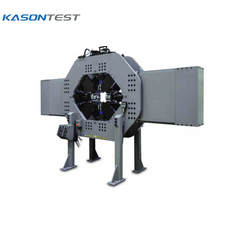
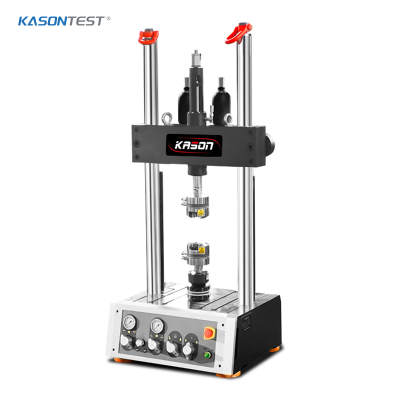
Planar Biaxial Test System.The biaxial tensile testing machine takes electronic servo control technology as the core, and can carry out two-way tensile tests of various metallic and non-metallic materials.

Planar Biaxial Test System
Planar Biaxial Test System
Planar Biaxial Test System.The biaxial tensile testing machine takes electronic servo control technology as the core, and can carry out two-way tensile tests of various metallic and non-metallic materials.
Request a QuoteProduct Details
Planar biaxial mechanical testing is critical for characterizing complex design structures, components, and orthotropic and anisotropic lightweighting materials.
Finding equipment that enables test engineers to simulate real-world conditions, however, can be challenging. This equipment needs to stress the specimen in multiple directions while allowing test engineers to exert a great deal of control over the process.
A Comprehensive Portfolio of Planar Biaxial Load Frames
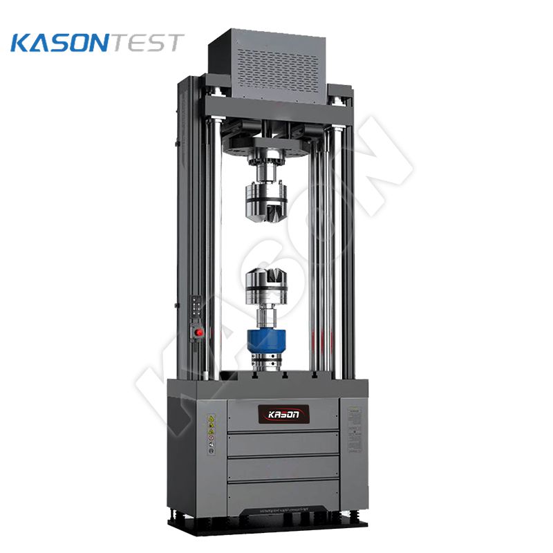
The planar biaxial system family features a complete array of ultra-stiff, standard servo-hydraulic load frames, dynamically rated to deliver loads ranging from 25 kN per actuator to 500 kN per actuator.
The actuators are arranged orthogonally (X and Y axes) in a single plane and the frame stands vertically, so one sees the X and Y planes as a front view. The +/-50 mm stroke (100 mm total stroke) actuators used in the frame are specially designed for planar biaxial testing with low internal oil volume to increase system stiffness.
Hydrostatic actuator bearings reduce friction and help ensure precise actuator positioning inside the cylinder. In addition, the system is designed with adjustable alignment apparatus in the load path that is used to remove specimen-bending strains.
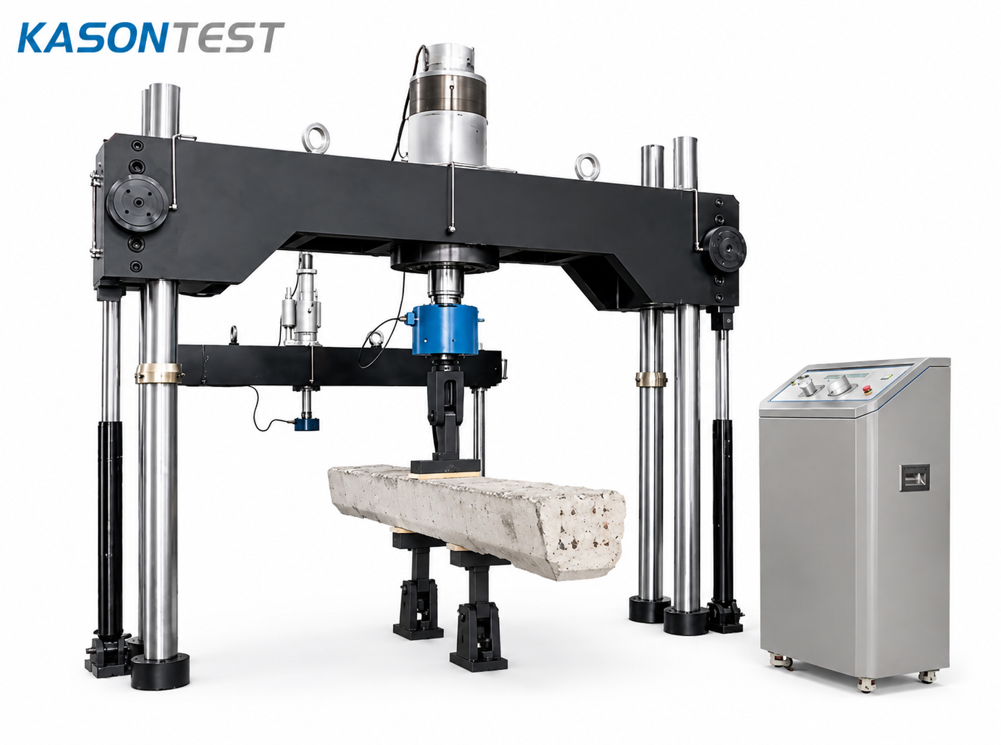
Offer two frame sizes for each load rating. The systems with smaller frames are suitable for ambient testing or can be used with induction heating; the larger frames have a sufficient test area to accommodate environmental chambers or furnaces.
Key system attributes
» A highly stiff frame and large specimen mounting area
» Compact design
» Low friction actuators with hydrostatic bearings
» High lateral stiffness that provides accurate test results and very high frame natural frequency
» Optional over-travel protection in X, Y, Z planes for system protection
» Optional acceleration compensation for high frequency work
Product parameters
|
FRAME DESCRIPTION |
HEIGHT |
WIDTH |
DEPTH |
WEIGHT |
SUGGESTED FLOOR SPACE |
|
25 kN compact |
1.9 m (75.6 in) |
1.0 m (39.4 in) |
0.9 m (36 in) |
550 Kg |
3 m x 3 m |
|
25 kN classic |
2.3 m (91.5 in) |
1.9 m (75.1 in) |
1.3 m (52.62 in) |
2000 Kg |
4 m x 4 m |
|
100 kN |
2.8 m (111 in) |
2.7 m (106 in) |
1.3 m (52 in) |
4500 Kg |
5 m x 3 m |
|
100 kN w/ Rot |
2.8 m (111 in) |
4.3 m (171 in) |
1.3 m (51 in) |
6500 Kg |
6 m x 3 m |
|
250 kN |
4.1 m (163.5 in) |
3.8 m (151.2 in) |
2.3 m (93.9 in) |
8000 Kg |
5.5 m x 3.5 m |
|
250 kN w/ Rot |
3.7 m (146 in) |
4.5 m (179 in) |
1.3 m (50 in) |
11000 Kg |
6 m x 3 m |
|
500 kN |
4.2 m (167 in) |
3.6 m (144 in) |
1.3 m (50 in) |
10000 Kg |
5.5 m x 3 m |
Download
| Name | Download |
|---|---|
| Planar Biaxial Test System.pdf |
Applicable industries

Related Products
-
Telephone:+86 15910081986
Address:NO.4715, JINGSHI WEST ROAD, HUAIYIN DISTRICT, JINAN, SHANDONG, CHINA
Mailbox:admin@jnkason.com
-
Testing machine equipment metallographic analysis hardness tester series
Non-destructive testing equipment Material analysis instruments
©2026 Jinan Kason Testing Equipment Co., Ltd.